ABSTRACT
Porous materials have attracted massive scientific and technological interest because of their extremely high surface-to-volume ratio, molecular tunability in construction, and surface-based applications.
Through my PhD work, porous materials were engineered to meet the design in selective binding, self-healing, and energy damping. For example, crystalline MOFs with pore size spanning from a few angstroms to a couple of nanometers were chemically engineered to show 120 times more efficiency in binding of large molecules.
In addition, we found building blocks released from those crystals can be further patched back through a healing process at ambient and low temperatures down to -56 ºC. When building blocks are replaced with graphenes, ultra-flyweight aerogels with pore size larger than 100 nm were made to delay shock waves. More stable rigid porous metal with larger pores (~um) was also fabricated, and its performance and survivability are under investigation.
Aside from experimental studies, we also successfully applied numerical simulations to study the mutual interaction between the nonplanar liquid-solid interface and colloidal particles during the freezing of the colloidal suspensions.
Colloidal particles can be either rejected or engulfed by the evolving interface depending on the freezing speed and strength of interface-particle interaction. Our interactive simulation was achieved by programming both simulation module and visualization module on high performance GPU devices.
SEQUENTIAL BINDING OF LARGE MOLECULES TO HAIRY MOFS
Materials and Method:
Materials
In our experiments, Cu(FMA) (4,4’-Bpe)0.5∙0.5H2O (Cu-MOFs) were used, where FMA is fumarateion C4H2O42-) and 4,4’-Bpe is 4,4’-vinylenedipyridine (C12H10N2). Cu-MOFs were synthesized after an established “shake-and-bake” method. 2.24 Briefly, a mixed solution of Cu(NO3) 2∙2.5H2O (0.0663 g, 0.285 mmol), H2FMA (0.0331 g, 0.285 mol), and 4,4’-Bpe (0.0260 g, 0.143 mmol) in H2O (25 mL) in a 30 mL glass vial was heated in a convection oven (DKN400, Yamato Scientific America, Inc.) at 100 °C for 24 h.
Characterizations:
X-ray diffractometry (XRD, Bruker AXS D8 Discover with GADDS) was conducted to examine the crystal structures of Cu-MOF, Cu-MOF-1, CuCl2∙(4,4’-Bpe) and CuFMA samples. The weighted average wavelength of the Cu Kα x-ray source was 1.5417.
Åtomic force microscopy (AFM, Dimension 3100 SPM system) was performed to reveal the surface morphology of the Cu-MOFs, crushed Cu-MOFs and its morphological developments in salt solutions with various concentrations. Before AFM imaging, the Cu-MOF crystals were soaked in the salt solutions for 10 minutes before washing and drying.
Results and Discussion:
Trapping of Large Molecules on Surface Defects
We first found that defects like cracks or edges in MOFs are effective traps for retaining large molecules like proteins. A simple mechanical crushing reveals more active sites and greatly enhances protein adsorption onto particular crystal planes .
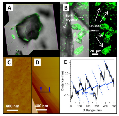
Confocal Fluorescent Microscopic Images of Protein (Gfps) Adhesion on (a) Bulk and (B) Crushed Cu-mof Crystals; Afm Images of (C) the Bulk and (D) Crushed Mof Crystal; (E) Section Analysis of (D) Along the Line Revealing the Surface Terraces With a Fringe Spacing of 0.77 Nm, Matching Crystal Planes of (200)s.
METAL–ORGANIC FRAMEWORKS CAPABLE OF HEALING AT LOW TEMPERATURES
Materials and Method:
Materials
Cu-MOFs crystals:Cu-MOFs were synthesized using the “shake-and-bake” method described.
Cu-MOFs powders and membranes: The powders were prepared by mechanically crushing as-synthesized Cu-MOFs crystals using a mortar and pestle.The Cu-MOFs membrane (>15 μm in thickness) for nanoindentation tests was obtained by drop-casting a 2.0 wt% water suspension of Cu-MOFs powders onto a piece of Si wafer.
The Cu-MOFs membrane (~ 25 μm in thickness) for three-point bending test, on the other hand, was prepared by drop-casting 5.0 wt% Cu-MOFs powder suspension on a Teflon film. After water was naturally dried, a freestanding membrane was harvested directly from the Teflon substrate.
Characterization and Modeling:
Sample characterizations: X-ray diffractometry (XRD, Rigaku Multiflex) was conducted to examine the crystal structures of the as-synthesized and healed Cu-MOFs samples. The weighted average wavelength of the CuKα x-ray source was 1.5417 Å.
Atomic force microscopy (AFM, Dimension 3100 SPM system) was performed to reveal the surface morphology of the Cu-MOFs and it sinner layersunder air and water environment. The Scanning Probe Image Processor software (SPIP, Image Metrology, Denmark) was used to analyze the depth profiles.
POROUS MATERIALS FOR ENERGY DELAY OF MILD SHOCK WAVE
Materials and method:
Synthesis of giant graphene oxide (GGO): Graphite flakes (Sigma-Aldrich, cat #332461, ~150 flakes) were oxidized using the improved method.4.16. A mixture of 72 mL concentrated H2SO4and 8 mL H3PO4(85 wt%) was added to a mixture of 0.6 g graphite flakes and 3.6g KMnO4. The reaction was stirred for 10 min at room temperature to obtain a greenish mixture. The greenish mixture was poured into 80 mL ice water with 1.0 mL 30% H2O2 and stirred for 2 hrs.
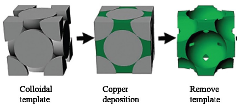
Sketch of the fabrication process of porous copper.
SOLIDIFICATION OF SUSPENDED COLLOIDS AT NONPLANAR
INTERFACE
Methodologies:
Simulation system setup
This directional freezing stage has been used in our or others experiments to observe the evolution of the solid-liquid interface. 5.27The cold (green,Tl) and hot blocks (red,Tl), with the temperature satisfying Tl< Tm< Th(Tm = the melting point of the suspension), are in good thermal conduction with the growth cell (rectangle).
The cold/hot blocks move at a constant speed Vs of, which is the equilibrium freezing speed of the process. As a result, a thermal gradient is created between these two blocks and a stable solidification interface is developed. The solid-liquid interface may push or engulf colloidal particles (white dots) depending on freezing conditions.

Sketch of our physical model in a unidirectional freezing.
Results and Discussion:
Instability and Morphology of 2d Solid-liquid Interface
In simulation of unidirectional freezing of a supercooled pure fluid, the surface instability can be achieved by introduction of latent heat along the moving interface. The latent heat from the phase change could lead to a negative temperature gradient (thermal supercooling) ahead of the interface even in unidirectional freezing. In this case, cellular and dendritic structures are observed in the simulation box (Figure 5.1(B&C)), which are similar to the structures developed by Kobayashi.
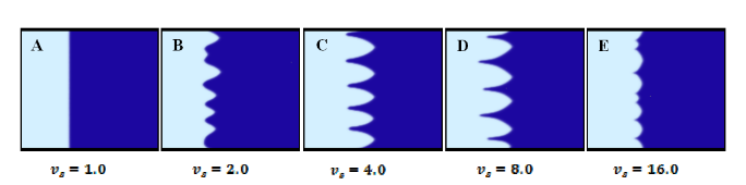
Interface Morphology Under Different Pulling Speed, Which Equals to the Freezing Speed Vs at Equilibrium.
CONCLUSIONS AND FUTURE WORK
The pore size in porous materials can range from a few angstroms to several micrometers, leading to broad applications in our daily activities as well as advanced technologies. Through my PhD studies, porous materials at different pore size regions are engineered to meet the design requirements and their novel applications are explored.
MOFs are crystalline microporous materials with pore size ranging from several angstroms to a couple of nanometers. While most studies utilized inner pores by regulating their interactions with small molecules, we chemically engineered Cu-MOFs to bind large molecules on the outer surfaces.
The engineered hairy MOFs by a touch of salt with Cu-MOFs have demonstrated 120 times more enhanced binding of GFPs, as well as the capability of stepwise binding. Therefore, our H-MOFs can serve as a microreactor for various biomolecular reactions through this consecutive and selective binding.
Significant energy delay has been observed in our graphene-absorbed glass microfiber
filter. However, graphene sheets are found to be hard to enter inner layers of glass microfiber due to the limitation of the pore size. Rigid porous metal thin films with micrometer pores are also fabricated and under investigation.
In the meantime, a temperature gauge can be installed to track the temperature fluctuation in the sample cup during Kolsky bar compression test. In order to fully understand the mechanism of air bubbles in energy delay of shock wave, quantitative measurements of trapped air (e.g. size, shape, connectivity) are required.
Source: University of Nebraska-Lincoln
Author: Zhanping Xu