ABSTRACT
Vacuum forming is a popular, cost effective method amongst large and small scale applications. The method is used to mold a material to the surface of a mold/pattern in order to create a negative copy for reproduction or an object in positive form.
The prototype vacuum forming system developed and documented herein is of a membrane-seal type that consists of three principle parts: radial platen, Hinged Frame and Platen Support Assembly, and a PVC surge tank.Each part is described in detail through design, manufacturing, and testing processes.
The design supports functional versatility, small scale molding,and uses readily available materials. Functional prototype testing was performed with the thermoplastic KYDEX® and multiple objects for mold examples. Results include successful proof of concept, design pros and cons, and findings based on functional testing.
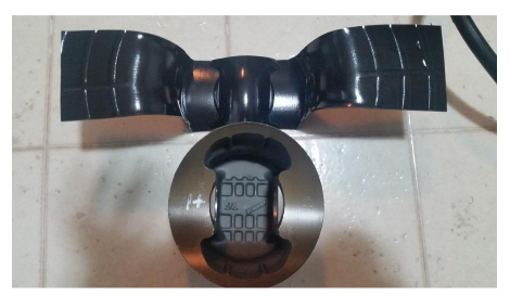
Piston Molding 2nd Attempt Mold Comparison.
REVIEW OF LITERATURE
History of Vacuum Forming:
Some of the first patents of vacuum or thermoforming machines and concepts came about in the 1930-1950 era. One of the first patents of vacuum forming, Patent No. 2,142,445 was filed on November 27th, 1936 by H.E. Helwig of Rohm and Haas Corporation containing a machine that used oil pressure in order to form a plastic sheet to a mold. The inner part of the sheet would not have any blemishes since it was only in contact with hot oil and the plastic sheet would cool as it was being pressed against the mold since the mold was water cooled(Rosen).
Vacuum Forming: How it Works:
Vacuum forming is a subset of manufacturing forming processes that uses the differential pressure between ambient atmosphere and a partial vacuum in order to pride sufficient force to shape a heated and softened thin sheet of thermoplastic material around the exposed surface of a moldor pattern.
As thin sheets quickly cool via conductive heat transfer to a temperature below the material’s heat deflection temperature (HDT), the speed of initial forming is critically important. In order to create a vacuum inside the forming system quickly, the volume of air contained between material/membrane and the mold/platen must be “dumped” or quickly removed by evacuating the air into an empty volume (a “surge tank”) that is connected to a vacuum pump.

Vacuum Thermo forming System(VTS) Example
Online Resources:
Multiple resources were used throughout the design and manufacturing processes. Each resource listed includes information that they provide and how it has been used in reference to the document. From professional vacuum forming design companies, KYDEX® manufacturing documents and specifications, to valuable online resources for technical information.
Hydraulics & Pneumatics:
The website Hydraulics & Pneumatics explains the fundamentals of vacuum, and how it works in a physical explanation and detailed description. The science behind vacuum and how it works is the true marvel in vacuum forming applications. Evacuating air between two enclosing objects is what creates the ability for the atmospheric pressure to work in such applications (Hydraulics & Pneumatics, 2012).
Engineering Toolbox:
The Engineering Toolbox is a great website as an engineering knowledge database. This site contains data from calculations and formulae to industry standard dimensional data for various applications (The Engineering ToolBox, 2014). A particularly useful part of this website was the dimensional data for pipe, specifically schedule 40 PVC dimensions.
Orthotics and Prosthetics (O&P) Edge:
The O &P Edge website is a resource for hobbyists and makers providing information for those who like to build things instead of buying them (Wickman, 2014). Of particular usefulness was information regarding sizing and economically building a surge tank for a vacuum forming system.
DESIGN
Platen:
The first iteration vacuum platen design began as a ½ inch thick, 2 foot square, solid surface acrylic known as Corian®, a material made by DuPont ® and typically used for countertops. The data supporting the structural integrity of the solid surface Corian® platen was given by specifications from DuPont®.
The compressive strength of Corian® according to the ASTM C365 test is 16,000 psi, which is more than enough to handle the compressive pressure under vacuum at 14.7 pounds per square inch (DUPONT, 2015).
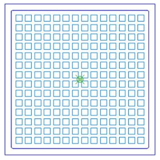
Square Grid Platen Design.
Hinged Frame and Platen Support/Base Assembly:
A Hinged Frame and Platen Support/Base Assembly was designed to support the platen and provide a path for the vacuum line. The upper portion, consisting primarily of a frame assembly which supports and suspends the thin flexible membrane, was attached to the upper surface of the Platen Support/Base Assembly using three (3) one inch steel commercial hinges. The lower portion, or Platen Support/Base Assembly, consists of three major sections: Upper Platen Support, Lower Platen Support, and Hinge Support.
Platen Support/Base Assembly:
The Platen Support/Base Assembly consisted of three basic parts. The Upper Platen Support was comprised of a 22 in x 23.5in x3/4in thick piece of medium density fiberboard(MDF). The Lower Platen Supportwas nominally an 18in x 18in x3/4 in thick piece of MDF.
Matching 1/2in x 1/4in deep channels were provided in the bottom face of the upper platen support and the top face of the lower platen support towards the right side of the base from the center to provide a passageway for the vacuum hose from the platen center fitting to the first isolation valve and surge tank.
Surge Tank:
The purpose of a surge tank is to evacuate the air trapped between the membrane and the platen as rapidly as possible to create a large differential pressure across the material surface to conform the pliable thermoplastic before it cools below the HDT. The surge tank design, is very simple.
The body of the surge tank is comprised of three separate parts: a length of 6 inch diameter schedule 40 PVC pipe, and two (2) 6in diameter schedule 40 PVC rounded end caps. Three (3) holes were drilled into the surge tank, one in an end cap and two in the cylinder. Two (2) ¼ in NPT adapters were threaded into the PVC, one on an end cap and one in the cylinder.
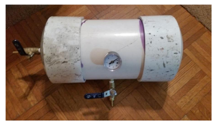
Surge Tank Post-Assembly.
MANUFACTURE
Platen:
The platen was fabricated using an AXYZ CNC gantry router for quality and accuracy. The platen’s radial design was created as a two dimensional(2D) AutoCAD drawing file. The 2D vector polyline geometry of the various centerline tool paths was imported into the ToolPath CAM system provided with the AXYZ CNC router.
Hinged Frame and Platen Support Assembly:
The two (2) parts of the frame assembly have separate manufacturing processes. The upper frame was created from a 22in x 22in x 3/4in piece of plywood by setting the saw fence 1.5in from the blade . The inner 19in x 19in area was removed using a hand saw. A drill press and 5/16 in drill bit were used to make the 28 through holes for the ¼-20 T-nuts.
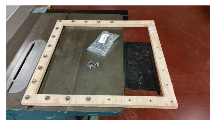
Insertion of T-nuts Into Upper Hinged Frame Assembly.
Platen Support/Base Assembly:
Components for the Platen Support/Base Assembly were produced with commonly available workshop tools: a 12 inch table saw, 12 inch pull saw, and drill press. Both the Upper and Lower Platen Supports were cut from two (2) two foot sections from a single 4 foot square sheet of 3/4 inch medium density fiberboard.
Surge Tank:
Several specialty tools were needed to manufacture the surge tank as well as chemicals for a proper seal and adhesion. The central section of the surge tank is a twelve (12) inch long section of 6 inch diameter schedule 40 PVC pipe. To insert and attach the valves and gauge, two holes were cut with a 7/16 in drill bit then followed by a ¼ NPT tap, one in the cylinder and the other in one of the end caps. The third hole was drilled into the cylinder with a “Q”(0.322inDIA) drill bit and 1/8 NPT tap for the vacuum gauge.
TESTING AND RESULTS
System Testing:
Testing began after final assembly to measure the initial capabilities and performance of the vacuum forming system. The surge tank was the first part of the system to be tested to ensure proper seal in each valve and threaded parts.After isolating the tank from ambient air by closing Valve A, a 2.5cfm commercial HVAC vacuum pump was used to evacuate the air from the surge tank until a vacuum of 27inHg (~13.3 psig) was reached.

Surge Tank Maximum Vacuum Reading.
VFS Standard Operating Procedures:
The various processes for using the vacuum forming system and molding any thermo-formable polymer sheet in this case KYDEX®, is very simple. The typical connections for the VFS must be made prior to any operations.
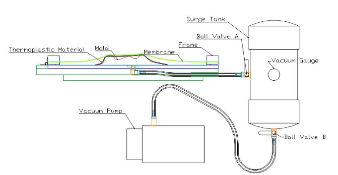
Vacuum Forming System Diagram.
Results:
Resulting attributes to the vacuum forming system and KYDEX® were discovered after several molding attempts with different objects. It was found that the material heating stage is the most important amongst the different processes when using this prototype VFS.
If the material was heated to too high a temperature, it created a very sticky surface characteristic and proved to be difficult to work with when being applied to the mold; much like working with extremely hot double-sided tape.
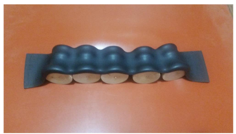
Candle Holder Molding Top View.
CONCLUSION
Overall, the prototype Vacuum Forming System worked very well and is expected to withstand a high number of operational cycles. All of the materials used in the manufacture of this vacuum forming system can sustain the ability to be used in this fashion consistently.
As an extension of this project, the vacuum forming system could be configured for “Food Safe” operation using a Nitrile membrane and the solid surface Corian platen material can be used for this purpose. Also, if the user desires to use this system as a Thermoforming system by using the hermoplastic material in place of a membrane, it can be adapted to do soas well.
With external funding, standardized testing with multiple materials could be undertaken using a standardized test mold/pattern. This standardized mold/pattern would consist of multiple pins and depressions in order to compare multiple material properties (primarily thickness) as well as different flexible membrane materials in different thicknesses.
This would show the ultimate limits of the vacuum forming system with different materials and show best case molding scenarios for different types of membranes and thicknesses. There are a couple recommendations as far as the forming system hardware and function. After further review and mold testing, it was determined that slotted frame hinges would benefit better to the function of the vacuum forming system.
The hinges used did not allow the frame assembly to rise and lower while vacuum was applied, which does not allow the foam seal between the frame assembly and platen to function to the fullest extent. Finally, the use of a commercial industrial oven for narrow range banding for precision temperature control and suspended material heating would be ideal. Again, this would require significant external funding.
Source: East Tennessee State University
Author: Andrew G. Smith