ABSTRACT
The goal of this work is to experimentally investigate the stable crack growth (SG) fracture behavior of AISI 4340 alloy steel. A series of mode I and mixed mode CG fracture test were carried out on 8 mm thick compact tension (CT) specimens subjected to quasistatic loading.
The wire cutting technique was used to introduce a prenotch/pre-crack of 0.05 mm root radius to the specimen. Five different loading angles II between the loading axis and the crack surface were employed; 90° (mode I), 75°, 65°, 60° and 50°. Five different ratios of original crack length to specimen width aJw were also employed 0.41, 0.42, 0.43, 0.44 and 0.45.
Different combinations of II and aJw were used. Data concerned with direction of initial crack extension load-load line displacement (L-LLD) diagrams, initiation and maximum loads, range of stable crack growth., crack blunting crack front geometry, fracture surfaces, and scanning electron microscope fractographs were obtained.
A noticeable blunting was observed prior the crack initiation. Although the crack commences its growth from a pre-notch / pre-crack of a straight front it has a considerable tunneling at each stage of stable crack growth. In mixed mode, the crack takes place along a straight-line path initially, inclined with the main crack at an angle equal to the direction of crack extension.
The loading angle \II and the initial crack length to the specimen width aJw ratio affect the SCG fracture behavior significantly. The direction of initial stable crack extension was determined through an elastic finite element analysis. There was reasonably good agreement between the experimental and the predicted results.
LITERATURE REVIEW
Introduction:
In this chapter literature relevant to linear elastic fracture mechanics (LEFM), crack extension through brittle materials elastic plastic fracture mechanics (EPFM), and mode I and mixed mode (I and II) stable crack growth are reviewed.
Fracture Mechanics:
Where cracks are difficult to avoid, a special methodology called fracture mechanics can be used to aid in selecting materials and designing components to minimize the possibility of fracture.
Fracture mechanics is a subset of solid mechanics that deals with the behavior of solid systems containing one or more cracks. Fracture mechanics is a relatively new area of solid mechanics research, with its foundation laid in the early 20th century. Already it has broad application in systems ranging in size from micrometer length scales (thin ftims, MEMS) up to kilometer length scales (earthquake fault lines).
Linear Elastic Fracture Mechanics (LEFM):
When possible, fields around a single crack tip are analyzed using Linear Elastic Fracture Mechanic (LFM) a this is the simplest model within LEFM any arbitrary crack tip stress state in a linear elastic isotropic homogeneous material can be decomposed into the unique linear combination of the three mutually orthogonal modes: symmetric in plane (mode I), antisymmetric in-plane (mode II), and out-of-plane (mode III). In other words, the cracked body can be loaded in anyone or a combination of the three loading (displacement) modes that are schematically depicted. Mode I is called the opening or tensile mode, where the crack walls, faces, move directly apart .
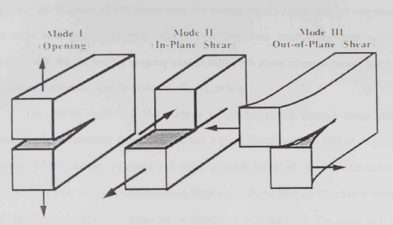
The Basis Modes of Loading (Crack Surface Displacement) That Can Be Applied to a Crack.
Unstable Path of Crack Extension:
The unstable crack extension takes place mostly immediately upon initiation through brittle materials. Therefore, it is of importance to know the initiation load, direction of initiation crack growth initiation and unstable crack path can be predicted. A number of criteria are available for the prediction of brittle fracture load (Pc) and direction of initial crack initiation (8).
Elastic-plastic Fracture Mechanics:
EPFM is used when the crack tip is not sharp and there is some crack-tip plasticity (blunting). EPFM is used to design materials such as lower-strength, highertoughness steels. For such more ductile material the assumption of small scale yielding may not be met disallowing LEFM analysis. The next level of fracture modeling is Elastic-plastic Fracture Mechanics (EPFM). In such cases the problem has to be treated elasto-plastically.
EXPERIMENTAL PROCEDURE
Introduction:
This chapter reports on: the selected material for the present investigation and its properties, the geometry of the specimens used for both tensile test and fracture test as well as procedure of fabrication, and testing.
Material:
The material selected for the present investigation is an aircraft quality AlSI 4340 steel alloy which is heat treatable, low alloy steel containing nickel, chromium and molybdenum. It is known for its toughness and capability of developing high strength in the heat-treated condition while retaining good fatigue strength.
It also combines deep harden ability with good ductility as well as good toughness and strength. It has sufficient carbon and alloy content to necessitate the application of preheat if cracking is to be avoided in a weld and associated heat affected zone.

Compact Tensions (CT) Specimen Geometry for Mode I and Mixed Mode Loading. Thickness T = 8 Mm.
Specimens Preparation:
Tensile Specimens Preparation
The tensile test specimen was made as per ASTM E811 990 (Test Methods for Tension Testing of Metallic Materials) recommendations.
Fracture Specimens Preparations
So, far there is no standard specimen configuration and test procedure available for mode I and mixed mode stable crack growth studies. The different configurations employed are compact tension (CT) So, three point bend (TPB) specimens crack bend bar, etc. The compact tension (CT) specimen was employed by some workers for both mode I and mixed mode stable crack growth study.
Fixture:
A fork-type fixture was designed and fabricated from AISI 4340 steel alloy material. The design based on the rigidity of the fixture. This fixture was designed so that both mode I and mixed mode fracture tests can be accommodated.
MODE I STABLE CRACK GROWTH
Experimental Studies:
The compact tension (CT) specimen for mode I stable crack growth. The test was conducted on 100 kN MTS machine under displacement controlled conditions. The specimens were loaded quasi-statically to the maximum load and beyond. The loading was done with a head speed of 0.1 mm/min. The load Vs load line displacements were recorded at suitable intervals of loading. The data were plotted to obtain the load-load line displacement diagrams.
Finite Element Analysis:
A two dimensional elastic-plastic finite element model for mode 1 analysis has been constructed using the program ANSYS 5.4, a commercial general purpose finite element package. The mechanical properties of the material Mode 1 stable crack growth in isotropic material shows symmetry along crack plane, as a result only half of the specimen was modeled.
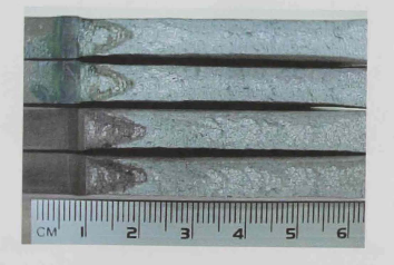
Sample Photograph of Crack Front Around Initiation and Maximum Load for Ajw = 0.43
MIXED MODE STABLE CRACK GROWTH
Finite Element Analysis:
A 2-D finite element model using ANSYS 5.4, has been used to determine the directions of initial stable crack extensions. All the analysis has been performed assuming a plane state of stress. Some investigators have shown that the direction of crack extension can be determined from the elastic stress analysis using the maximum tangential principal stress or the maximum principal stress criteria. This method has been adopted for all case studies.
CONCLUSION
Some of the conclusions which can be made are as follows:
- Both the initiation and maximum loads increase as the loading angle Psi decreases from mode I case (i.e.,Psi = 90°)
- The ratio of maximum to initiation loads varies in the range of 2.0 to 22. For the whole range of loading angles tested.
- Both the initiation and maximum loads decrease as adw ratio increases in both modes I and mixed mode. The initial spurt of extension is generally moving in mixed mode than in the mode I.
- There is a considerable blunting in both mode I and mixed mode before stable crack
growth (SCG) initiation. - The amount of stable crack growth increases as aJw ratio decreases and loading angle Psi reduces from 90°. The range of stable crack growth is more in case of mode 1
- There is a considerable tunneling in both mode I and mixed mode. The tunneling is generally more in the case of mixed mode. The extent of tunneling increases with
crack extension. - The crack extents almost along a straight course initially in mixed mode loading. The
angle of direction from the initial crack increases as the loading angle reduces from
mode I case (PSi = 90°). - The directions of initial crack extension predicted through an elastic finite element analysis in conjunction with the maximum tangential principal stress (MTPS) criteria agree well with the experimental results.
- The fracture surfaces show tension dominated dimpled fracture in mode I and mixed mode.
- The spread of the plastic zone, at initiation, along the line of cracks extension
is more than that in the transverse direction.
Source: United Arab Emirates University
Author: Mohammed Juma Humaid Al-Ghafri